
A Glow Wire with Thermocouple is a testing apparatus design to perform Glow Wire testing which is carried out on plastic materials used in electrical devices. It assesses the plastic’s ability to resist ignition and to self-extinguish if ignited. As a safety test, its purpose is to prevent the start or the spread of fire in the event of an electrical component becoming overheated.
The fire hazard test and combustion performance test, simulate under fault or overload conditions, The thermal stress caused by a heat source or ignition source, such as a hot element or overload resistance, over a short period of time to assess the risk of ignition. The test is suitable for lighting equipment, low-voltage electrical appliances, household appliances, machine tools, electrical machines, electric tools, electrical instruments, information technology equipment, electrical affairs equipment, electrical connectors, auxiliary parts and other electrical and electronic products and their components, production, and quality inspection department. Also suitable for insulation materials engineering plastics or other solid combustible materials industry.
Description of a Pyrosales Glow Wire with Thermocouple.
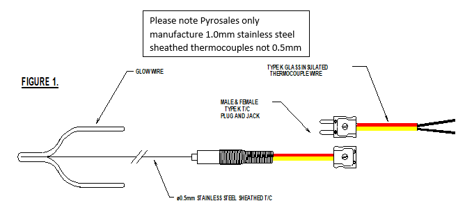 The ‘Glow Wire with Thermocouple’ consists of a formed piece of 4mm diameter heating element wire (80% Nickel / 20% Chromium) with a 1.0mm diameter Type K (Chromel vs. Alumel)™ mineral insulated metallic sheathed thermocouple thermally fixed 3.5mm into the inside point of the Glow-Wire, as shown in Figure 1. Each thermocouple is calibrated by Pyrosales. against standards maintained by the Company specifically for this purpose, which are traceable to the CSIRO, National Measurement Laboratory, and a NATA Report of Calibration issued.
A suitable measuring device, such as a RKC Digital Temperature Indicator or a handheld indicator such as the DM305TC, can be supplied by Pyrosales to measure the millivolt output from the thermocouple.
Brass supporting studs, as, do not form part of a standard ‘Glow Wire with Thermocouple’, however can be optionally fitted by Pyrosales. The remaining test equipment should be fabricated or supplied by others.
Unpacking a Pyrosales Glow Wire with Thermocouple.
Considerable care should be taken when unpacking the ‘Glow Wire with Thermocouple’ as the fine diameter thermocouple measuring element can be easily and permanently damaged. Carefully cut the bonding tape and remove the supportive packing material from around the assembly and lay the assembly on a safe flat surface.
Mounting the Pyrosales Glow Wire Thermocouple.
How the ‘Glow Wire with Thermocouple’ will be used will depend on the Test requirements and the equipment to which it will be attached. If 4mm diameter brass mounting studs are to be fixed to the assembly, considerable care must be taken in silver soldering (or otherwise fixing) these to the Glow Wire arms; as during this process, permanent damage in the form of ‘cold working’ can occur to the fine gauge mineral insulated thermocouple assembly particularly near where it is fixed to the inside of the Glow Wire. A temporary thermocouple support is provided to minimise damage occurring to the thermocouple during shipment and prior to use.
During the mounting procedure, it will be necessary to properly support the thermocouple assembly to ensure that it is not broken or stressed, particularly in the area adjacent to where it enters the inside part of the Glow Wire tip.
Making the Pyrosales Glow Wire with Thermocouple Electrical Connection.
The Type K (Chromel vs. Alumel)™ mineral insulated thermocouple assembly is supplied with two high temperature glass covered leads, to which a yellow coloured Type K (Chromel vs. Alumel)™ two-pin miniature socket is attached. A matching male plug is provided to which 3m of duplex glass covered 20 AWG Type K (Chromel vs. Alumel)™ thermocouple wire is connected.
To measure the temperature of the thermocouple it will be necessary to connect it to a suitable monitoring device. A modern design direct reading digital temperature indicator with loC resolution is considered suitable.
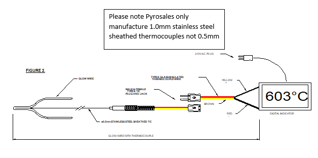
Figure No. 2 shows a typical connection arrangement. Such a measuring instrument will normally incorporate some form of thermocouple automatic temperature reference junction compensating arrangement and, as a result, it is essential that proper Type K (Chromel vs. Alumel)™ thermocouple extension wire is run from the supplied yellow male plug to the measuring device terminals.
Important: Most Type K (Chromel vs. Alumel)™ thermocouple assemblies, extension wire & fittings sold and used in Australia comply with American National Standard MC 96.1, entitled ‘Temperature Measurement Thermocouples’. Standard MC 96.1 identifies the below listed products: -Type K Thermocouple – Nickel Chromium vs. Nickel Aluminium (Chromel vs. Alumel)™ – Overall Colour – Brown with optional yellow fleck, or yellow Positive Conductor – Nickel Chromium (Chromel)™; Colour Code Yellow Negative Conductor – Nickel Aluminium (Alumel)™; Colour Code Red Type K Connectors – Colour Code Yellow
When connecting electric power to the measuring device (assuming it is mains powered), follow the appropriate instructions provided by the supplier. Warning: It is possible that there may be an interaction between some measuring devices and the electric power applied to the Glow wire (assuming this to be 50 Hz A.C.) via the measuring thermocouple. Special care is taken in the manufacture of the ‘Glow Wire with Thermocouple’ to limit this likelihood, however, some equipment (digital indicators with poor common mode rejection specifications) may be found to be unstable or experience offsets. The RKC Digital Temperature Indicator or a handheld indicator such as the DM305TC has been found to be suitable for this application.
After all electrical connections have been made, carefully support the thermocouple in the most suitable manner (this may include tying or fixing the outer metal 1.0mm diameter sheath) to an appropriate bracket (can be specially fabricated) or available fixture. This should be done in such a way that the least possible stress is placed on the area where the thermocouple enters the inside section of the Glow-Wire. Ensure that allowance is made not to restrict movement of the thermocouple outer sheath due to expansion of the assembly when heated. During this procedure, remove the temporary thermocouple support.
Using the Pyrosales Glow Wire with Thermocouple
Cleaning of the Glow Wire will be required from time to time, as burnt residue builds up on the tip. Very considerable care must be exercised in removing burnt residue from the Glow Wire tip, as damage to the fine gauge thermocouple assembly can easily occur during this procedure. In practice, it has been found that a soft suede metal bristle cleaning brush (as commonly used for cleaning suede shoes) is suitable for this purpose. When cleaning the Glow Wire tip it is desirable to brush carefully toward the Glow Wire tip to prevent damage occurring to the thermocouple.
Calibrating the Pyrosales Glow Wire with Thermocouple
Each Type K (Chromel vs. Alumel)™ thermocouple assembly is calibrated at 960oC by Pyrosales, using a reference Type R (Platinum 13% Rhodium vs. Platinum) rare metal thermocouple assembly and appropriate test equipment, prior to assembly in the Glow Wire. A NATA (National Association of Testing Authorities, Australia) Report of Calibration is issued, which lists the serial number of each ‘Glow Wire with Thermocouple’, the measured temperature value and the uncertainty of the overall calibration, together with other appropriate data.
The millivolt output of fine gauge Type K (Chromel vs. Alumel)™ mineral insulated thermocouples is known to drift when used for long periods of time at elevated temperatures. In most instances, testing work using the ‘Glow Wire with Thermocouple’ will be carried out on sample materials below the maximum required temperature of 960oC, hence subsequent drift in the thermocouple assembly will be minimised. The need for, or frequency of, re-certification of the thermocouple assembly will depend on individual operating parameters. However, in most instances, it is expected that, due to its frail nature, the thermocouple assembly will fail prior to the need for re-certification.
Should re-calibration of a ‘Glow Wire with Thermocouple’ be required, place a foil of pure silver (at least 99.8% pure), 2mm square and 0.06mm thick, on the upper face of the tip of the Glow Wire. Heat the Glow Wire by increasing power in the usual manner until the silver foil just melts (being 960oC). Special care must be taken to increase the temperature of the Glow Wire very slowly as it approaches the melting point of the silver foil. It will be necessary to precisely note when the foil begins to melt and ensure that power to the Glow Wire is maintained in a steady state condition at that time to minimise the chance of quickly passing through the melt temperature of 960oC. It may be necessary to repeat the measurement several times to gain experience and obtain repeatable results.
Trouble Shooting Measuring Problems with the Pyrosales Glow Wire with Thermocouple.
Should the validity of the thermocouple or its associated wiring or readout instrumentation become suspect, the following troubleshooting procedure can be followed, e.g.: –
Repairing the Pyrosales Glow Wire with Thermocouple.
If the Type K (Chromel vs. Alumel)™ thermocouple assembly is damaged (typically broken), The complete ‘Glow Wire With Thermocouple’ must be discarded and replaced with another certified unit.
CONTACT FOR MORE INFORMATION OR A QUOTE