
PTFE
How to identify an RTD and Thermocouple?
To determine whether a sensor may be a thermocouple or an RTD is to measure the resistance using a Volt Ohm Meter. If the sensor has two lead wires, measure the resistance between the two leads. If the sensor is a thermocouple, you are just measuring the resistance of that length of wire.
Most RTDs are limited to a maximum temperature of 1000 degrees Fahrenheit. In contrast, certain thermocouples can be used to measure up to 2700 degrees Fahrenheit.
RTD FUNDAMENTALS
 Pyrosales Resistance Temperature Detectors (RTDS) are specially designed to ensure precise and repeatable temperature versus resistance characteristics. The sensors are constructed in a unique strain‐free manner and use only high quality RTD elements. Ceramic, wire‐wound elements, flat film technology elements, or military specified anti‐vibration elements are used as per the customer’s requirement to ensure the most suitable specification is supplied.
Features and Benefits
Accuracy. A special process combines strain‐free construction with full winding support for dependable, accurate readings in standard RTD elements, and in flat film elements where platinum is etched onto a substrate.
High signal‐to‐noise output. Increases the accuracy of data transmission and permits greater distances between the sensor and the measuring equipment.
Interchangeability. Strain‐free construction and precision trimming allow elements from different lots to be substituted without re-calibration.
Sensitivity. Self‐heating is minimised, allowing precise measurement. The temperature coefficient (alpha) is carefully controlled at the industry standard while insulation resistance values exceed IEC‐751 standards.
Standardisation. Elements are available to meet or exceed the requirements of various standardisation agencies. IEC‐751 standard tolerance classes A and B respectively are very well suited for industrial applications. Tolerance classes up to 1/10th DIN can also be supplied where higher accuracy is demanded. Physical and chemical stability over a wide temperature range. Pyrosales use a highly controlled manufacturing process. Standard elements are built to resist mechanical vibration and shock, however, where there is high exposure to mechanical vibration, special manufactured military specification thick film RTD elements can be supplied to suit the application.
Repeatability. All elements exceed IEC‐751 repeatability values even after long exposure to
temperatures within the operating range.
Applications 
• Air conditioning and refrigeration servicing
• Food Processing
• Stoves and grills
• Textile production
• Plastics processing
• Petrochemical processing
• Microelectronics
• Air, gas, and liquid temperature measurement
• Exhaust gas temperature measurement.
When to use RTDs
• When accuracy and stability are a requirement of the customer’s specification.
• When accuracy must extend over a wide temperature range.
• When area, rather than point‐sensing, improves control.
• When a high degree of standardisation is desirable.
Advantages 
• Linear over wide operating range
• Wide temperature operating range
• High temperature operating range
• Interchangeability over wide range
• Good stability at high temperature
Disadvantages
• Low sensitivity
• Higher cost than thermocouples
• No point sensing
• Affected by shock and vibration
• Requires three or four‐wire operation
Installation
The main consideration when installing an RTD element is that there is sufficient immersion to ensure that the RTD is not averaging the temperature of the process and equipment or structure outside the process. The RTD is not a point‐measurement device like a thermocouple, so there is an active sensing area that needs to be fully immersed to ensure that the RTD is measuring the actual process temperature. A good thermal transfer along the shaft of the sensor for 40mm is critical when installing a thermowell. The active sensing area of an RTD sensor. This area will vary depending on the length of the RTD element used in the construction. Sensors can be designed to give an average temperature indication.
Choice of Sensor
There are many options to consider when choosing the correct RTD element for your requirements:
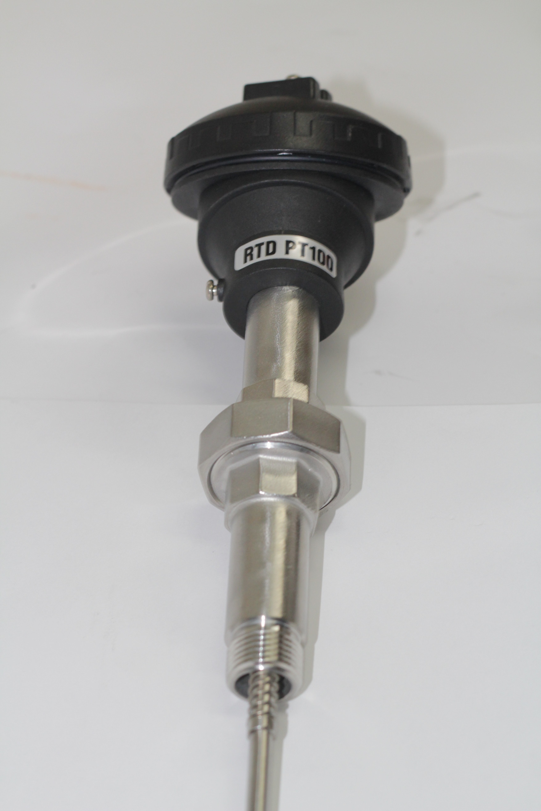
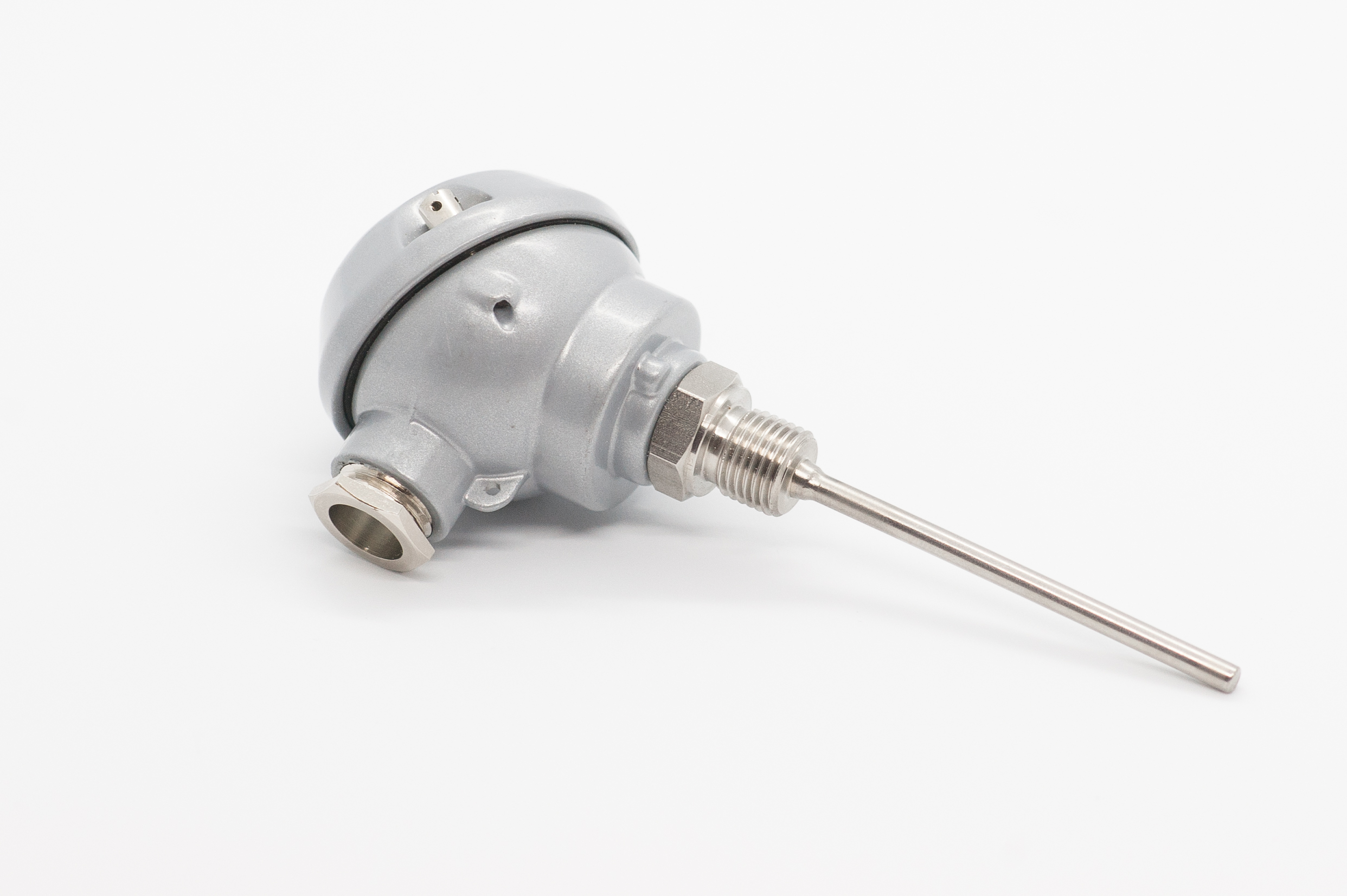
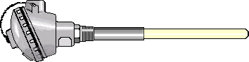
Temperature rating Tolerance, accuracy, and interchangeability.Time response Distance from control or measuring equipment. The most common construction used is to place the RTD element and attached wires into a closed end metal tube, pack the tube with a vibration dampening and/or heat transfer material such as alumina powder, and seal the open end of the tube with an epoxy, silicone, or ceramic cement. The metal tubes most commonly used in RTDs are made of 316 stainless steel (used to approximately 480°C) or Inconel® (used to approximately 650°C). The vibration dampening/heat transfer materials used vary widely in the temperature range. These materials are selected by the manufacturer to provide the optimum performance based on the maximum temperature expected in use.
Another common construction is to use mineral insulated metal sheathed (MIMS) cable, where the RTD element is inserted into a drilled hole and attached to nickel or copper wires insulated by magnesium Oxide (MgO). The end is then insulated with MgO and the end welded closed, and the other end has extension wires attached before sealing as above. Epoxy sealing compounds are typically never used above 200 to 260°C. Ceramic cements can be exposed to temperatures of 1200°C or more but require a sealant to keep moisture out of the cement and the vibration dampening/heat transfer material beneath. The material with the lowest temperature capability in a platinum RTD is usually the wire and insulation used in its construction. Pyrosales offer two constructions, low temperature, and high temperature. In low temperature constructions, PTFE insulated nickel plated copper wire is used to connect to the RTD element. The stainless-steel tube is alumina powder filled to provide support to the element and has an epoxy seal. This construction is usually limited to 250°C. High temperature constructions use either nickel wire and ceramic insulators, or MIMS cable containing nickel wires. The nickel wire and ceramic construction is alumina powder filled to support the element. The sealant used will depend on the temperature rating of the transition point. Both types of construction can be used to approximately 650°C, however with careful selection of element, and use of Inconel® sheathed MIMS cable, this can be extended to approximately 850°C.
Tolerance, accuracy, and Interchangeability:
Tolerance and accuracy are the most misunderstood terms in temperature measurement. The term tolerance refers to the degree of uncertainty or possible error at a specific point. Accuracy refers to an infinite number of tolerances over a specified range. For example, RTDs contain a sensing element that is manufactured to have a specific electrical resistance at a specific temperature. The most common example of this requirement is what is known as the DIN/IEC standard. To meet the requirements of the DIN/IEC standard, an RTD must have a resistance of 100 Ohms ±0.12% (or 0.12 Ohms) at 0°C to be considered a Grade B sensor (a Grade A sensor is 100Ohms ±0.06%). The tolerance of ±0.12Ohms applies only to the resistance at 0°C and cannot be applied to any other temperature. Below is an interchangeability table for Class A RTDs, which provide the user with a table of tolerances at specific temperatures. See Lead wire resistance has a major impact on the measured resistance. The ability to compensate for this
additional resistance will affect the type of assembly chosen and the system accuracy. The most common type of assembly is the 3‐wire RTD. Here, the lead wire resistance is compensated for in a bridge circuit. For highest accuracy, the only option is to use a 4‐wire RTD where lead wire resistance error is eliminated.
Time Response
 When selecting the style of assembly that best suits your process, consideration must be given as to how quickly the sensor will react to a change in temperature. If a thermowell is used, the response time will be dramatically increased, and care must be taken in the design of the thermowell/sensor system. The thermowell bore should closely match the RTD diameter so that good thermal contact is achieved, thus maximising thermal transfer.
If quick time response is a criteria, the smaller the element and probe, the quicker the time response will be. There will be a trade‐off then between the achievable response time and suitability of the sensor to stand up to the process environment.
Distance from control or measuring equipment
Where the RTD assembly is installed will dictate the type of RTD required. If the control/measuring point is relatively close to the installed sensor, then it is practical to cable directly to the instrument. For longer distances, examine the input specifications of the instrument to determine whether the lead wire impedance will be too large. In these instances, the use of a 4‐20mA transmitter is recommended. (4‐20mA transmitters convert the resistance to current for transmission over 2‐wires with minimal losses).
Troubleshooting
Problems associated with RTD assemblies tend to be straightforward and easily fixed. As RTD elements are susceptible to damage by vibration or mechanical shock, the most likely problem will be that the element is open circuit. Depending on the type of assembly, this can be determined easily with a multimeter. Drift problems are often more subtle. As Platinum is easily contaminated, the fundamental resistance can be changed by the introduction of impurities, and the resistance to temperature response can be
dramatically different to that of pure platinum. In this instance the only method of determining whether there is an error is to calibrate the RTD sensor.
Strengths and Weaknesses of RTDs
Each type of temperature sensor has particular strengths and weaknesses.
RTD Strengths:
 RTDs are commonly used in applications where repeatability and accuracy are important
considerations. Properly constructed Pt100 RTDs have repeatable resistance versus temperature characteristics over time. If a process will be run at a specific temperature, the resistance of the RTD at that temperature can be determined in the laboratory and it will not vary significantly over time. RTDs also allow for easier interchangeability since their original variation is much lower than that of thermocouples. For example, a Type K thermocouple used at 200°C has a standard limit of error of ±2.2°C. A Pt100Ohm DIN, Grade B platinum RTD has interchangeability of ±1.3°C at this same temperature. RTDs also can be used with standard instrumentation cable for connection to display or
control equipment, where thermocouples must have corresponding thermocouple wire to obtain an accurate measurement.
RTD Weaknesses:
In the same configuration, you can expect to pay more for an RTD than for a base metal thermocouple. RTDs are more expensive than thermocouples because there is more construction required to make the RTD, including manufacture of the sensing element, the hooking up of extension wires, and assembly of the sensor. RTDs do not perform as well as thermocouples in high vibration and mechanical shock environments due to the construction of the sensing element. Industrial RTDs are also limited in temperature to 650°C whereas thermocouples can be used as high as 1700°C.
THERMOCOUPLE FUNDAMENTALS
12‐15
Service Life
 Useful thermocouple life is a very difficult prediction to make, even when most of the details of an application are known. And unfortunately, such information is often very hard to determine. The very best test for any application is to install, use, and evaluate the in‐use performance of a design that is thought likely to succeed. The recommendations, and non‐recommendations, listed under the thermocouple type descriptions are a good place to start when first selecting an assembly style to install in a process.
DECALIBRATION AND DRIFT
Stability
All thermocouples are subject to calibration drift with use, it is just a matter of how much, and how fast this may happen. Thermocouple performance is critically dependent upon absolute uniformity of both physical and chemical properties along the entire length of the circuit. When thermoelement materials are produced, careful steps are taken to assure that this uniformity (or homogeneity) is achieved. In use, different parts of the circuit experience different conditions of heat, chemical exposure, etc., and as a result such parts do change in physical structure and composition from the original thermoelement wire. Because the thermoelectric emf resulting from a given temperature difference is sensitive to changes in the chemical and metallurgical properties of the wire, the total emf produced by a used
probe can be different from an otherwise identical new one under the same conditions. The
changes are usually small (often negligibly small) over appreciable periods of time. But under adverse conditions, it is possible to realize large drifts at rapid rates. To achieve long and reliable thermocouple life, the usual strategy is to operate the device comfortably under its maximum temperature and provide it with the cleanest possible environment in which to work. Enclosures, such as sheaths, protecting tubes, and thermowells, are the usual means of controlling the conditions that surround the thermoelements themselves.
What can go wrong
 Protecting tubes, sheaths, and even thermowells, can fail due to corrosion or mechanical damage. Processes can go over temperature and exposure thermoelements to higher than anticipated temperatures. If a sensor controlling a process drifts low in its output, the process, in response to its controller, may as a result be forced to temperatures higher than intended. Base metal assemblies are vulnerable to attack by a number of chemical agents. They can also be altered by unfavourable operating conditions. As supplied, noble metal thermocouple wire of good quality has very low impurity levels. Consequently, it is susceptible to contamination that can effect its thermoelectric properties. Platinum is especially sensitive to the presence of free silicon, with which it can combine to form a eutectic alloy that will melt at or below normal service temperatures. High‐purity insulators and protecting tubes for precious metal assemblies as well as careful attention to cleanliness in handling, are therefore essential to help prevent this occurring. Human error can be a contributing factor as well. Controls may be improperly set, connections may be improperly made, and inappropriate action in response to the operating conditions may
be taken by mistake. Redundancy in instrumentation combined with training and responsibility are the usual means to combat these kinds of errors.
TROUBLESHOOTING
The approach
To assess the problem, check if the system performance seems to be reasonable for the
conditions: Do changes in the controls produce a logical result? What about the product? Does its condition correspond with what the instruments are saying?
How to test a used thermocouple
Firstly, it is not always practical to remove a suspect thermocouple from service and ‘test’ it in another place. Once the device is used means that it may no longer be homogeneous. Subjecting an inhomogeneous thermocouple to a different set of temperature gradients, even if only subtly different, can result in a different output and reading. Recalibrating a used thermocouple will certainly yield a ‘number’, but that number will probably be meaningless in the thermocouple’s place of use. The best way to evaluate a used thermocouple is to ‘probe’ the location by placing a new thermocouple that has a known output, alongside the suspect one in an operating process, and compare the readings. If it is not practical to have two sensors in place at the same time. Remove the suspect probe and replace it with another one known to be good. Then, as long as the good probe is located in the same place as the removed one has been, and the process has not changed during the exchange, the readings from the two probes can be compared. Note that it is not necessary to keep and use an unlimited supply of new probes for these tests. A few suitable replacement devices can be kept available, selecting one for testing use. Under
normal circumstances, thermocouple drift, or degradation, is a gradual and very slow process. A single replacement probe can therefore be used numerous times to probe a process and be considered reliable for repeated tests. And, when a drifted probe has been found, the test probe may simply be left in place as a working sensor, while the next replacement becomes the test device.
System tests
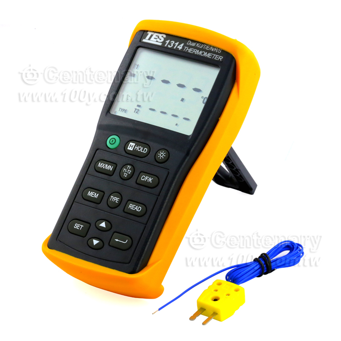 A useful instrument for troubleshooting thermocouple systems is a portable temperature indicator. A number of these devices can operate with two or more different thermocouple types, and some offer an ‘output’ function that will produce an electrical output to simulate a thermocouple operating at any temperature of choice. In use, the instrument is normally attached to the wires of a circuit being tested at some convenient access point, such as in a connecting head. Care should be taken to ensure that the correct polarity is maintained. In Australia, we use the ANSI colour code where the negative is
always RED. There, the output of an operating sensor may be monitored and evaluated. Or, using an instrument’s ‘output’ function, a simulated thermocouple signal may be sent back to the circuit’s permanent indicator or controller to verify proper operation of the rest of the circuit.
When driving a signal back towards an instrument, it is usually necessary to break one side of the circuit to avoid ‘loading’ the portable tester by the low resistance of the thermocouple itself. Sections of extension wiring in thermocouple circuits can also be checked for proper connections with a portable tester. The section being tested should be electrically isolated from the rest of the loop, and one end of an extension wire pair should be shorted together. If a tester is connected to the opposite end of the shorted pair, the tester should indicate the approximate temperature of the shorted end. Note that if both ends of the extension pair happen to be at the same temperature, it may be necessary to warm the shorted end a little and verify that the tester ‘sees’ the temperature change correctly. The possibility of an incorrect, reversed connection is being checked in this test.
Summary – RTD or Thermocouple:
Both thermocouples and RTDs are useful sensors for determining process temperature. RTDs provide higher accuracy than thermocouples in their temperature range because platinum is a more stable material than are most thermocouple materials. RTDs also use standard instrumentation wire to connect to the measurement or control equipment, which can reduce the overall installation cost. Thermocouples are generally less expensive than RTDs. They are more durable in high vibration or mechanical shock applications and are usable to higher temperatures. Thermocouples can be made smaller in size than most RTDs and they can be formed to fit a particular application.