
 A thermocouple is a pair of dissimilar metals joined at one end and elsewhere isolated electrically from each other. It produces a small electrical signal that can be used to monitor temperature. A popular notion is that the EMF (Electric and Magnetic Fields) is generated at the tip or hot end of the thermocouple at the junction between the two metals. This notion is completely incorrect. The EFM is not localised to the tip but is dispersed throughout the lengths of each leg. The total EMF generated in a thermocouple is the difference between the EMF’s in both legs. This is due to the Seebeck coefficient of the metal or alloy used. (Seebeck Effect is a phenomenon in which a temperature difference between two dissimilar electrical conductors or semiconductors produces a voltage difference between the two substances. This can be applied to thermal-to-electrical energy conversion. The Seebeck effect was discovered in 1821 by Thomas Seebeck). This coefficient is a measure of how the electrons are coupled to the environment, to the metal lattice, and, on a larger scale, to the grain structure.
It is sensitive to changes in the chemical and physical features of the metal and will change if the metal is contaminated, oxidised, strained or heat treated. Since all those processes depend on temperature and a thermocouple, because of its usage, experiences non-uniform temperature fields, there will be non-uniform changes in the Seebeck coefficient and therefore the thermocouple output. The wires thereby acquire a thermoelectric imprint or “signature”. Any change in the environment will affect the thermocouple output. A typical change is immersion depth. A change in thermocouple output resulting from reducing the immersion depth could be considerable. For example, a 24 AWG nickel-based thermocouple would only drift about 1oC in 16 hours, while monitoring a temperature of 1000oC, yet, if its immersion depth is decreased the output could change a further 15oC. Therefore, it is advisable to have thermocouples installed in a fixed position.
What is a Thermocouple Junction?
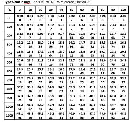
Thermocouples have two junctions, a hot junction, where the dissimilar metals are joined, and a cold junction. The cold junction is referenced to 0oC. Thermocouple outputs vary depending on the types of metals used. There are international tables, which are used to determine EMF values at different temperatures for different types of thermocouples. A problem that occurs is that the cold junction is usually at a temperature other than 0oC. Let us assume that we wish to determine the temperature of a process using a voltmeter to measure the mV output and a glass thermometer to measure the cold junction temperature. If we have a signal output of 9.340 mV and cold junction temperature of 27oC, the value of 9.340 mV should not be fed directly into the reference tables, because it is inappropriate. If we did, it would read 300oC, and if the cold junction temperature were added, as is a common notion, then a temperature of 327oC would be obtained. Let us now compare this with the correct result. The measured value is 9.340mV, which is the temperature gradient from 300oC to 27oC. What is missing is the gradient from 27oC to 0oC, which is 0.712 mV. Therefore, the correct mV output is 9.340 + 0.712 which equals 10.052 mV. When we look up the table, we read a temperature of 320oC – a difference of 7oC.
Manufacture of MIMS Thermocouples
Care must be taken during the manufacture of thermocouples to ensure that contaminants are not present, and in the case of MIMS, that moisture is not present prior to sealing the thermocouple. To ensure that contaminants are not created during welding, TIG welding techniques are used. By using an argon shield you achieve an oxygen-free weld that ensures that scaling and oxidisation do not occur. It is also good practice to weld close the thermocouple with the same material as the sheath if MIMS thermocouples are being manufactured. Moisture is eliminated by either placing the thermocouple in a drying oven or heating the thermocouple with an oxy-torch to ensure that any moisture in the magnesium oxide insulation has been driven out. These techniques are used for the hot junction. The cold junction must also be protected against contaminants i.e. it should be housed in a suitable enclosure that will inhibit the ingress of foreign gases, particles, and moisture.
There are basically three types of hot junction:
• Exposed
• Grounded
• Ungrounded
The choice of the hot junction will be dependent upon the response of the thermocouple, contamination hazards, physical restraints, and electrical earthing considerations.
 Base Metal Thermocouples
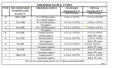
The base metal thermocouples are made from basic metallic element alloys (iron, copper & nickel). Base metal thermocouples with the ANSI standard are E, J, K, N & T, and are usually used for temperatures up to1200oC.
Rare Metal Thermocouples
These are often designated as “ Noble Metal “ thermocouples and are generally designated to
thermocouples with conductors made from platinum and/or platinum alloys. They consist mainly of the type B, R & S, and are typically used for high-temperature applications above 1200oC.
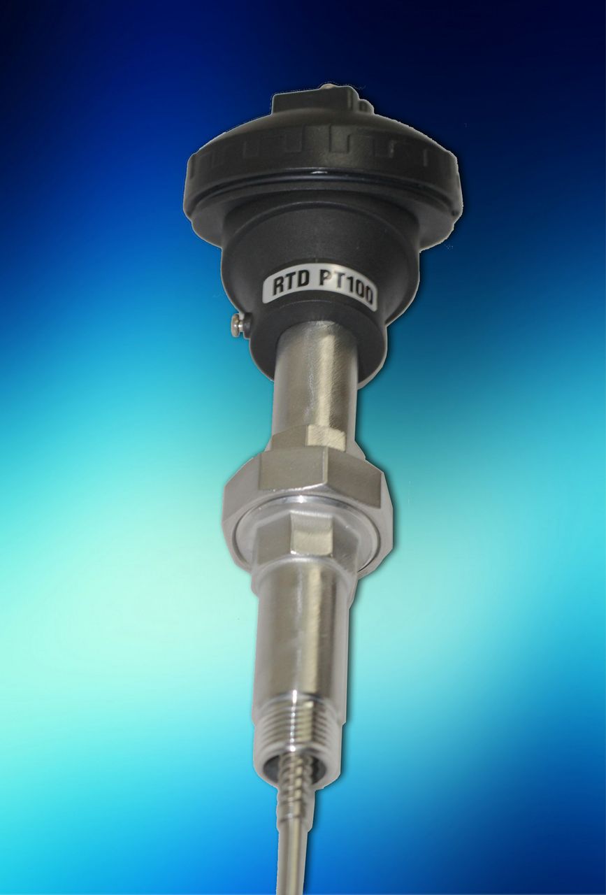
Mineral Insulated Thermocouples
Developments in sheathing materials & integral sheath/elements combinations allow the use of K & N thermocouples for higher temperatures. The mineral insulated thermocouples can be classified as a modern development. The mineral insulated metal sheathed (MIMS) thermocouple was introduced about 50 years ago, and it has revolutionised the temperature measuring industry. It has provided a compact design where the element is packaged in a protective environment.
THERMOCOUPLE FUNDAMENTALS
Service Life
Useful thermocouple life is a very difficult prediction to make, even when most of the details of an application are known. And unfortunately, such information is often very hard to determine. The very best test for any application is to install the unit, use, and evaluate the in-use performance of a design that is thought likely to succeed. The recommendations, and non-recommendations, listed under the thermocouple type descriptions are a good place to start when first selecting an assembly style to install in a process.
DECALIBRATION AND DRIFT
Stability
All thermocouples are subject to calibration drift with use, it is just a matter of how much, and how fast this may happen. Thermocouple performance is critically dependent upon absolute uniformity of both physical and chemical properties along the entire length of the circuit. When thermoelement materials are produced, careful steps are taken to assure that this uniformity (or homogeneity) is achieved. In use, different parts of the circuit experience different conditions of heat, chemical exposure, etc., and as a result, such parts do change in physical structure and composition from the original thermoelement wire.
 Because the thermoelectric emf resulting from a given temperature difference is sensitive to changes in the chemical and metallurgical properties of the wire, the total emf produced by a used probe can be different from an otherwise identical new one under the same conditions. The changes are usually small (often negligibly small) over appreciable periods of time. But under adverse conditions, it is possible to realize large drifts at rapid rates.
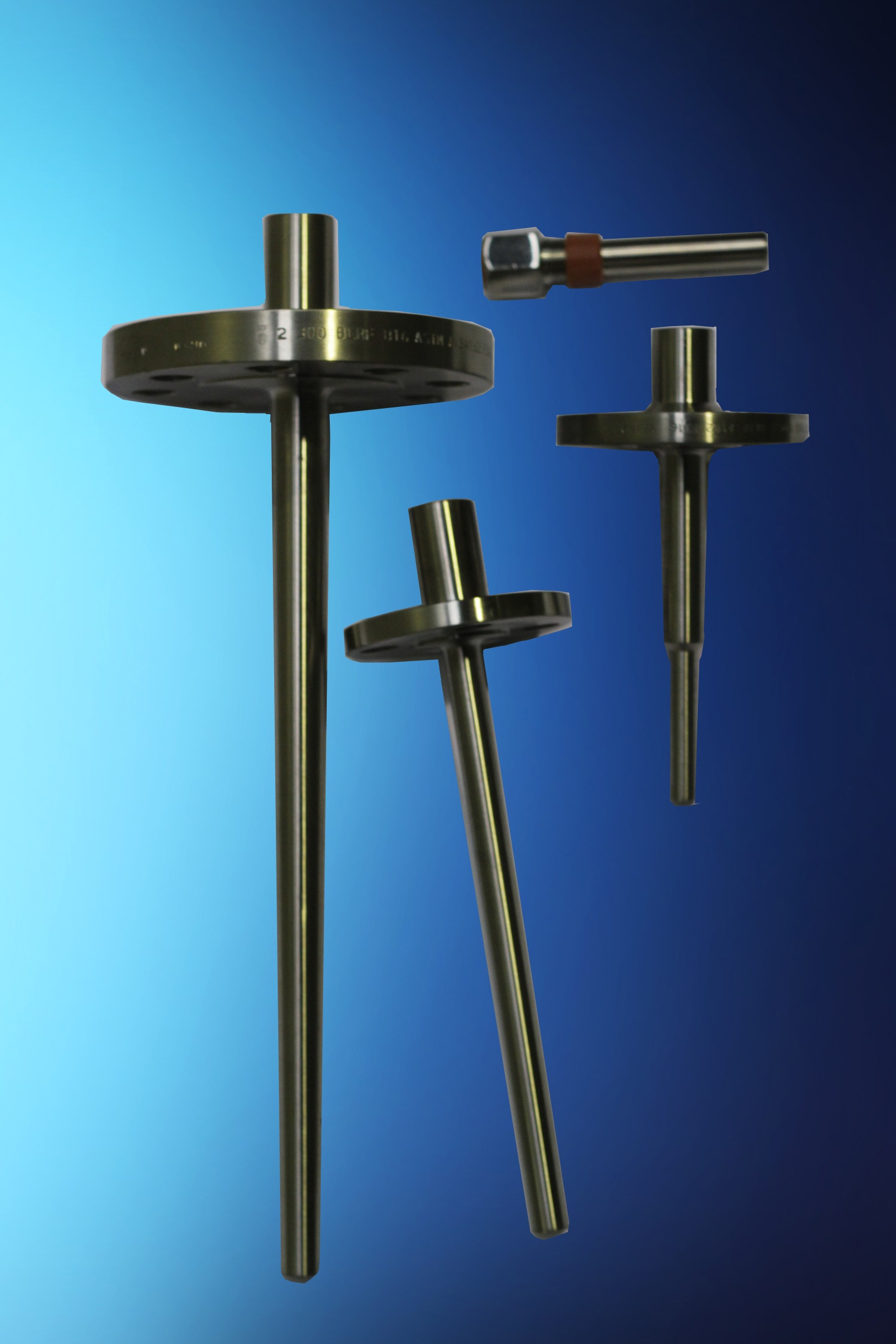
To achieve long and reliable thermocouple life, the usual strategy is to operate the device comfortably under its maximum temperature and provide it with the cleanest possible environment in which to work. Enclosures, such as sheaths, protecting tubes, and thermowells, are the usual means of controlling the conditions that surround the thermoelements themselves.
What can go wrong
Protecting tubes, sheaths, and even thermowells, can fail due to corrosion or mechanical damage. Processes can go over temperature and exposure  thermoelements to higher than anticipated temperatures. If a sensor controlling a process drifts low in its output, the process, in response to its controller, may as a result be forced to temperatures higher than intended. Base metal assemblies are vulnerable to attack by a few chemical agents. They can also be altered by unfavourable operating conditions. As supplied, noble metal thermocouple wire of good quality has very low impurity levels. Consequently, it is susceptible to the contamination that can affect its thermoelectric properties. Platinum is especially sensitive to the presence of free silicon, with which it can combine to form a eutectic alloy that will melt at or below normal service temperatures. High-purity insulators and protecting tubes for precious metal assemblies as well as careful attention to cleanliness in handling, are therefore essential to help prevent this occurring.
Human error can be a contributing factor as well. Controls may be improperly set, connections may be improperly made, and inappropriate action in response to the operating conditions may be taken by mistake. Redundancy in instrumentation combined with training and responsibility are the usual means to combat these kinds of errors.
TROUBLESHOOTING
The approach
To assess the problem, check if the system performance seems to be reasonable for the conditions: Do changes in the controls produce a logical result? What about the product? Does its condition correspond with what the instruments are saying?
How to test a used thermocouple
Firstly, it is not always practical to remove a suspect thermocouple from service and ‘test’ it in another place. Once the device is used means that it may no longer be homogeneous. Subjecting an inhomogeneous thermocouple to a different set of temperature gradients, even if only subtly different, can result in different output and reading. Recalibrating a used thermocouple will certainly yield a ‘number’, but that number will probably be meaningless in the thermocouple’s place of use.
The best way to evaluate a used thermocouple is to ‘probe’ the location by placing a new thermocouple that has a known output, alongside the suspect one in an operating process, and compare the readings. If it is not practical to have two sensors in place at the same time. Remove the suspect probe and replace it with another one known to be good. Then, if the good probe is in the same place as the removed one has been, and the process has not changed during the exchange, the readings from the two probes can be compared.
Note that it is not necessary to keep and use an unlimited supply of new probes for these tests. A few suitable replacement devices can be kept available, selecting one for testing use. Under normal circumstances, thermocouple drift, or degradation, is a gradual and very slow process. A single replacement probe can therefore be used several times to probe a process and be considered reliable for several repeated tests. And, when a drifted probe has been found, the test probe may simply be left in place as a working sensor, while the next replacement becomes the test device.
System tests
 A useful instrument for troubleshooting thermocouple systems is a portable temperature indicator. A number of these devices can operate with two or more different thermocouple types, and some offer an ‘output’ function that will produce an electrical output to simulate a thermocouple operating at any temperature of choice.
In use, the instrument is normally attached to the wires of a circuit being tested at some convenient access point, such as in a connecting head. Care should be taken to ensure that the correct polarity is maintained. In Australia, we use the ANSI colour code where the negative is always RED. There, the output of an operating sensor may be monitored and evaluated. Or, using an instrument’s ‘output’ function, a simulated thermocouple signal may be sent back to the circuit’s permanent indicator or controller to verify the proper operation of the rest of the circuit. When driving a signal back towards an instrument, it is usually necessary to break one side of the circuit to avoid ‘loading’ the portable tester by the low resistance of the thermocouple itself.
Sections of extension wiring in thermocouple circuits can also be checked for proper connections with a portable tester. The section being tested should be electrically isolated from the rest of the loop, and one end of an extension wire pair should be shorted together. If a tester is connected to the opposite end of the shorted pair, the tester should indicate the approximate temperature of the shorted end. Note that if both ends of the extension pair happen to be at the same temperature, it may be necessary to warm the shorted end a little and verify that the tester ‘sees’ the temperature change correctly. The possibility of an incorrect, reversed connection is being checked in this test.
 Pyrosales engineers are available to consult on various stages of any project, from the development and planning of a new project to modifying or upgrading an existing facility. Our staff is here to provide you with assistance and recommendations to ensure the best outcome and value. We are happy to visit our clients on-site or conduct meetings from one of our offices.
Pyrosales Pty Ltd has been assessed and approved by QAS International Ltd to ensure we adhere to quality management systems, standards, and guidelines. We continue to hold this certification by maintaining our work and quality practices: ISO 9001 Certificate Number A1066AUS 1066AU 20-21