
A Thermocouple is a sensor made with two different metal wires connected at the sensing end. The voltage measured on the other end reflects the temperature being measured. Although the accuracy can be slightly lower than an RTD, they have the most extensive temperature range from -200 °C to 1750 °C and are generally more cost-effective.
To simplify, a temperature sensor does just that, it senses the temperature of any content needing to be measured, whether they be solids, liquids, or gases. In some cases where these Thermocouples and RTDs are connected directly to a PLC, the result of the measurement accuracy is sometimes worse than expected. This loss of accuracy is often caused by electromagnetic interference, (EMI). By converting thermocouple and RTD signals to industry standard 4-20 mA current, errors due to EMI can be effectively eliminated.
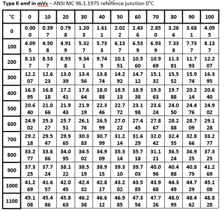
 Thermocouples create a voltage signal of less than 50 mV, and a thermocouple has practically no ability to create a current flow. Therefore, any device that measures a thermocouple must have a very high input resistance, (usually 1 million Ω or more).
The combination of a low mV signal and no current flow makes thermocouples behave like an antenna. Electrical noise from 50/60 Hz power mains, burst noise from lightning, static electricity, radio frequency interference from portable radios, commutator noise from electric motors and many other sources of electrical noise can be “received” by a thermocouple – and the longer the wires are, the more opportunity there is to “receive” electrical noise.
Can you clean a thermocouple?
Yes, you can clean a thermocouple, but the task must be done with a light touch. Remove the thermocouple from the process assembly, using a steel wool or emery cloth, lightly clean the tip removing any build up.
Cleaning a thermocouple is not a fix for an issue, such as inaccurate readings.
THERMOCOUPLE FUNDAMENTALS
Service Life
Useful thermocouple life is a very difficult prediction to make, even when most of the details of an application are known. And unfortunately, such information is often very hard to determine. The very best test for any application is to install the unit, use, and evaluate the in-use performance of a design that is thought likely to succeed. The recommendations, and non-recommendations, listed under the thermocouple type descriptions are a good place to start when first selecting an assembly style to install in a process.
Decalibration and Drift:
Stability
 Because the thermoelectric emf resulting from a given temperature difference is sensitive to changes in the chemical and metallurgical properties of the wire, the total emf produced by a used probe can be different from an otherwise identical new one under the same conditions. The changes are usually small (often negligibly small) over appreciable periods of time. But under adverse conditions, it is possible to realize large drifts at rapid rates.
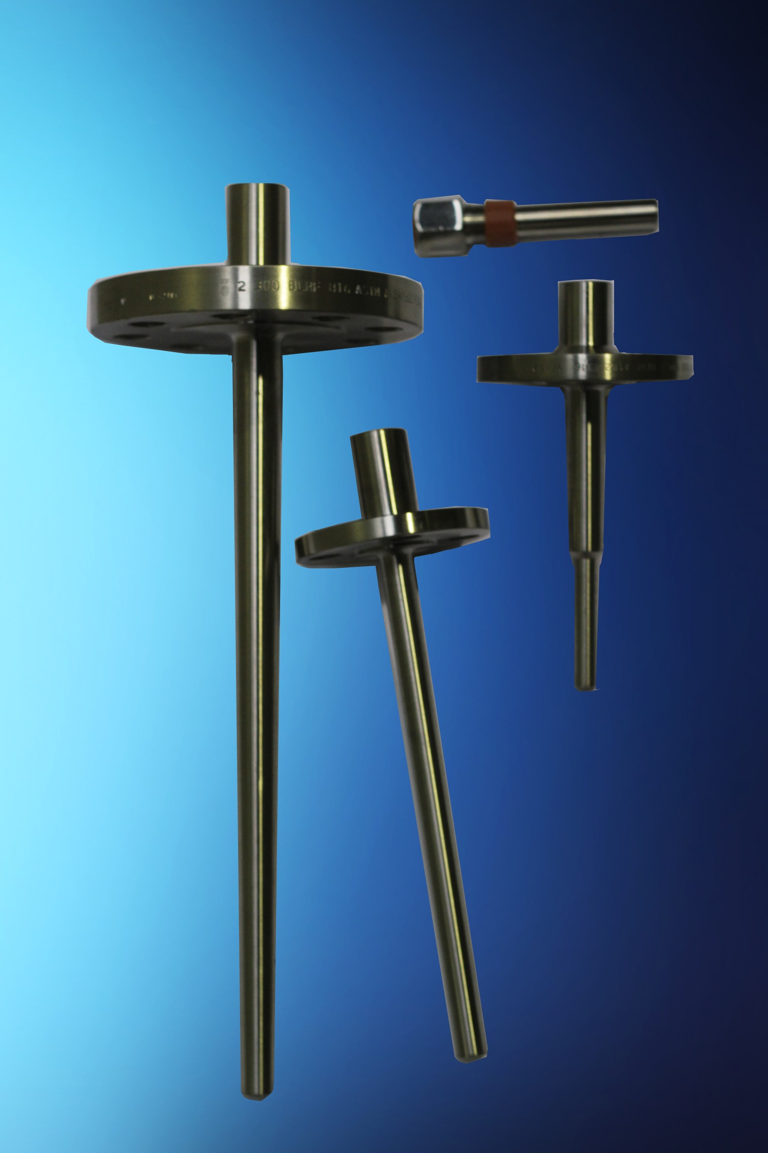
To achieve long and reliable thermocouple life, the usual strategy is to operate the device comfortably under its maximum temperature and provide it with the cleanest possible environment in which to work. Enclosures, such as sheaths, protecting tubes, and thermowells, are the usual means of controlling the conditions that surround the thermoelements themselves.
What can go wrong?
 Protecting tubes, sheaths, and even thermowells, can fail due to corrosion or mechanical damage. Processes can go over temperature and exposure thermoelements to higher than anticipated temperatures. If a sensor controlling a process drift low in its output, the process, in response to its controller, may as a result be forced to temperatures higher than intended. Base metal assemblies are vulnerable to attack by a few chemical agents. They can also be altered by
System tests:
A useful instrument for troubleshooting thermocouple systems is a portable temperature indicator. A number of these devices can operate with two or more different thermocouple types, and some offer an ‘output’ function that will produce an electrical output to simulate a thermocouple operating at any temperature of choice.
In use, the instrument is normally attached to the wires of a circuit being tested at some convenient access point, such as in a connecting head. Care should be taken to ensure that the correct polarity is maintained. In Australia, we use the ANSI colour code where the negative is always RED. There, the output of an operating sensor may be monitored and evaluated. Or, using an instrument’s ‘output’ function, a simulated thermocouple signal may be sent back to the circuit’s permanent indicator or controller to verify the proper operation of the rest of the circuit. When driving a signal back towards an instrument, it is usually necessary to break one side of the circuit to avoid ‘loading’ the portable tester by the low resistance of the thermocouple itself.
Sections of extension wiring in thermocouple circuits can also be checked for proper connections with a portable tester. The section being tested should be electrically isolated from the rest of the loop, and one end of an extension wire pair should be shorted together. If a tester is connected to the opposite end of the shorted pair, the tester should indicate the approximate temperature of the shorted end. Note that if both ends of the extension pair happen to be at the same temperature, it may be necessary to warm the shorted end a little and verify that the tester ‘sees’ the temperature change correctly. The possibility of an incorrect, reversed connection is being checked in this test.