
How do you measure pressure-flow?
In industrial plants, safe operations and efficiency are directly linked to business sustainability, financial performance, and long-term feasibility. That is why flow measurement, temperature measurement, and pressure measurement are so important. One way to measure pressure flow is using a multistage orifice assembly. The first record of the use of orifices for the measurement of fluids was by Giovanni B. Venturi, an Italian Physicist, who in 1797 did some work that led to the development of the modern Venturi Meter by Clemons Herschel in 1886. It has been reported that an orifice meter, designed by Professor Robinson of Ohio State University was used to measure gas near Columbus, Ohio, about 1890. About 1903 Mr. T.B. Weymouth began a series of tests in Pennsylvania leading to the publication of coefficients for orifice meters with flange taps. At the same time, Mr. E.O. Hickstein made a similar series of tests at Joplin, Missouri, from which he developed data for orifice meters with pipe taps.
What is multistage orifice assembly?
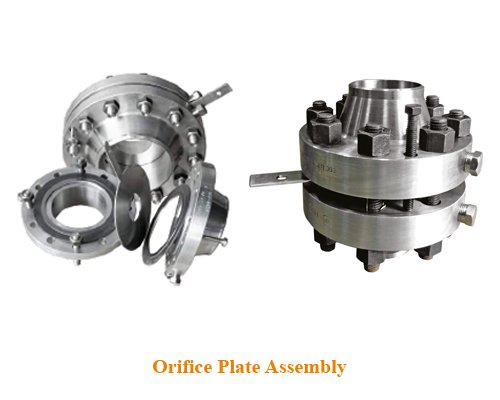 Pyrosales manufacturer orifice assemblies which are another type of measuring flow with high differential pressure meters effectively removing cavitation and flashing conditions. It also helps in killing pressure and thus effectively acting as a pressure reducing element. These are basically used to detect the flow of fluids, gasses, steam, steam water, acids, alkalises, crudes, high viscous fluids, fluids with solid particles, condensation liquids. Multistage assemblies lead to a precise measure of differential pressure leading to the most precise flow rate taking care of all factors of fluid cavitation related to its vapour pressure. The design is applicable from ½” to 64” of flow measurement. It is measured at right angles to the flow direction, In an averaging Pyrosales can design and obtain Multistage assemblies the kinetic energy of the flowing fluid is transformed into potential energy for measurement of fluid flow velocity by effectively abruption to 40% recovery in between two stages and thus, effectively removing the choking content of the fluid in gas and steam and removing cavitation in the liquid state thus essentially reducing industrial noise and restricting to below 80 decibels. Applications: n Gas and Liquid Flows n High-Pressure Drops Prevents: n Cavitation and Flashing in Liquid flows n Choked flow in gases. n Excessive Noise / Vibration
Restriction orifice plates have traditionally been used to reduce pressures in GAS AND LIQUID FLOWS by forcing the flow through a restricted bore. The precise pressure drop is produced by accurately calculating the orifice bore, having considered all the relevant process and flow conditions. Where very HIGH-PRESSURE DROPS in liquid flows are required
MULTISTAGE RESTRICTION ORIFICE ASSEMBLIES may be required to achieve the desired pressure drop whilst preventing problems such as CAVITATION, FLASHING, and high NOISE and VIBRATION levels.
CAVITATION is a potentially damaging, erosive condition that occurs when the internal pressure of the liquid passing through the orifice falls below its vapour pressure, and vapour bubbles form. Further downstream from the orifice the pressure recovers sufficiently to collapse the bubbles with extreme violence. Cavitation calculations are performed during the design stage of a Multistage RO to calculate cavitation factors at each stage in the orifice assembly.
FLASHING is a similar phenomenon to cavitation except that the process pressure never recovers sufficiently to collapse the gas bubbles resulting in two-phase flow – liquid and gas – downstream of the orifice. Erosion of pipe work and valves and other instrumentation can occur due to the impact of liquid droplets carried at high speed in the vapour flow.
CHOKED FLOW IN GASES – also known as critical flow – occurs when too large a pressure drop is attempted across a single orifice plate, or when too large flows are forced thru a lesser inlet pipe size. In such cases the flow through the orifice will become sonic, at which point no further increase in flow can be achieved by either increasing the upstream pressure or lowering the downstream pressure. Pyrosales multistage RO which will enable staged reductions in pressure to prevent choked flow occurring.
 Pyrosales Multistage ROs are manufactured from a wide range of materials and are engineered to meet specific project process conditions and requirements. Plates are usually welded into pipe with a separation of one pipe diameter, the number of plates and orifice bores being determined by calculation. Process connections to existing pipe work can be either standard process flanges or machined ends suitable for butt welding.
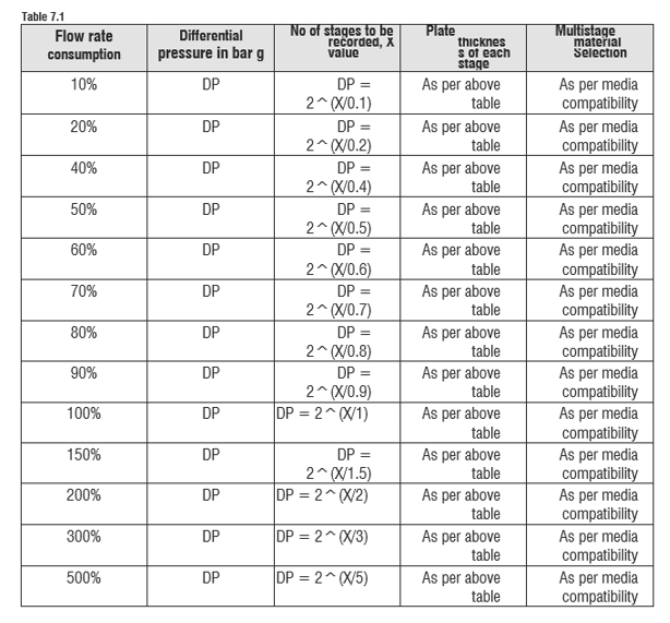
The process of designing the multistage assemblies for calculated value assembly is also defined depending on the final stages applicable for flow measurements, please refer to the table below:
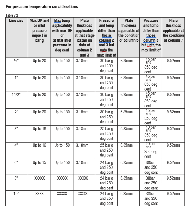
Other temperature and pressure combinations and your solutions, please revert to Pyrosales Pty Ltd and design team.
For example: Line size is 3” and flow rate is at 500% consumption and the pressure drop is 120 bar g and temperature is 500oC.
Thus, now to remove cavitation and effectively reduce noise within 80 decibels, for an application of steam water.
Solution and how to proceed:
Step 1: Since 500% consumption thus as per table above DP= 2^(X/5), therefore DP= 120 = 2^(X/5) thus X=33.7 stages for a perfect noise to within 70 decibels and choking is nil and thus increase the plant energy cost. If not given, then the noise level is 200 decibels at say 7 stages and a lot of energy is sapped and flow is lost, and further plant life will be reduced as more energy is required to drive flow.
Step 2: Thus 34 Stages are noted. Step 3: Divide 120/34 this = 3.53 bar drop per stage.
Step 4: As per above table, first impact of flow is 120 bar at 500oC, plate thickness works out to be min 28mm for 3” thus.
Step 5: Second stage inlet shall be 120 – (3.53×1.6) (since 40% recovery of press only at 1D distance of the second plate) =114.352 bar g but at 500oC.
Step 6: Thus, second stage plate thickness shall be same as 28mm as stage 1.
Step 7: This way onward calculations can be done, and all stages of plate thickness can be calculated for all 34 stages.
Step 8: After all calculations are completed the net result shall be … no choking, no cavitation, no noise beyond 70 decibels.
Just for information the noise level for above calculation come down to 66 decibels from a whopping 201 decibels. Such is the product applicability of Pyrosales Multistage design for measuring flow.
Remember Multistage assemblies from Pyrosales do measure flow and allow the maximum efficiency of the plant with high accuracy and no loss of flow concept, thus increasing the life cycle of the assembly, the plant life.